When designing a Digital-to-Analog Converter (DAC), engineers often encounter challenges stemming from signal distortion, noise, and poor resolution. These problems can derail the performance of even the most sophisticated systems.
These challenges are especially prevalent in high-precision applications like CNC machinery, robotics, or motion control systems, where DACs are integral to converting digital control signals into smooth, actionable analog outputs. Minor missteps in DAC design can lead to calibration issues and erratic system behavior, causing expensive delays and rework.
In this blog, we’ll cut through the complexity and focus on the essential components and principles that form the backbone of a reliable DAC design. We’ll explore how to minimize noise, optimize resolution, and ensure your DAC works smoothly in mission-critical systems.
Quick Recap
Precision Control: Resolution and step size determine the DAC's ability to deliver precise movement and positioning in systems like CNC and robotics. Higher resolution means finer control.
Monotonicity: A DAC must be monotonic to ensure stable, predictable motor behavior and avoid erratic movement in motion control systems.
Essential Components: DACs rely on key elements, such as digital input interface, voltage reference, and output conditioning, to deliver smooth, accurate analog signals for high-precision tasks.
Broad Applications: DACs are crucial in servo systems, robotics, and automation, converting digital signals into actionable analog outputs for precise control.
What is a Digital to Analog Converter?
A Digital-to-Analog Converter (DAC) is an electronic circuit that converts digital data, typically binary (1’s and 0’s), into an analog signal, such as a voltage or current. This conversion is critical in systems that require an analog output from digital control signals.
One of the primary specifications of any DAC is its resolution, which directly impacts its accuracy and the quality of the analog signal produced. Resolution is typically described in bits or step size; a higher resolution means better control over the analog output, with smaller voltage or current steps between each digital input.
Why Do We Need DACs?
While computers and digital systems are widely used in processing data at incredible speeds, they cannot directly interact with the analog world.
Consider audio or video processing: we use digital cameras and microphones to capture analog signals, converting them into digital data. After editing, however, we need a DAC to convert that digital data back into analog signals, which we can then hear through speakers or view on screens.
In applications like CNC systems and motion control, DACs are crucial. They convert digital control signals from systems like LinuxCNC into smooth, precise analog outputs that drive motors and actuators.
Without accurate DAC design and implementation, even the most advanced systems would suffer from noise and imprecise control, leading to poor performance and reliability.
With that in mind, let's look at some real-world applications where DACs are critical.
3 Key Applications of DAC
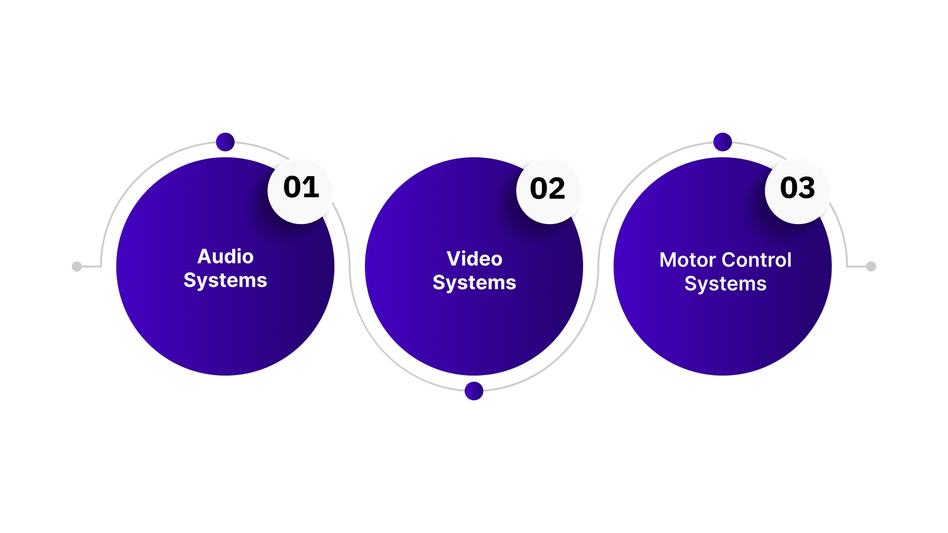
Digital-to-Analog Converters (DACs) are crucial in systems that convert digital signals to analog. Below are key applications where DACs play a vital role:
1. Audio Systems
Audio signals are inherently analog but are often stored and processed digitally (e.g., MP3, WAV files). DACs in audio systems or sound cards convert these digital signals back into analog, allowing the amplifier to adjust volume, treble, and bass before the signal reaches the speakers. Without DACs, digital audio files would be unplayable on analog systems.
2. Video Systems
Digital video players use DACs to convert digital video signals to analog, enabling playback on analog monitors. For example, while modern devices use HDMI or DVI ports for digital output, DACs convert the signal when analog output options like composite ports are used, ensuring compatibility with older equipment.
3. Motor Control Systems
DACs are essential in motor control applications. Microcontrollers generate digital signals to control motor speed or position. These signals are converted into analog outputs by DACs, allowing the motor to respond accordingly. This is especially critical in embedded systems, robotics, and automation, where precise motor control is necessary.
These examples highlight how DACs bridge the gap between digital devices and analog systems, enabling seamless operation across a wide range of technologies.
Now that we’ve covered key applications, let’s break down how DACs work to achieve these functions.
How Does a DAC Work?
A Digital-to-Analog Converter (DAC) converts digital binary data into an analog voltage or current. The data is represented as bits (1s and 0s), with each bit having a weight determined by its position. Starting from the rightmost bit, the weight of each bit follows the formula 2^n, where n is the bit's position, starting from 0.
For example, in the binary number 10011, the weights are calculated as:
Bit weight of the 4th bit (from the left) = 2^4 = 16
Bit weight of the 3rd bit = 2^3 = 8, and so on.
To calculate the analog value, multiply each bit value (either 0 or 1) by its corresponding weight:
1 × 2^4 = 16
0 × 2^3 = 0
0 × 2^2 = 0
1 × 2^1 = 2
1 × 2^0 = 1
Now, add the results together: 16 + 0 + 0 + 2 + 1 = 19.
This is the process a DAC follows to convert digital data (like 10011) into an analog output. The digital input is transformed into an analog signal by adding the weighted values of each bit.
Understanding how DACs work leads us to explore the different options available for various applications.
Types of DACs
When designing or selecting Digital-to-Analog Converters (DACs) for precision systems like CNC machinery or motion control, understanding the underlying architectures is crucial. The two most common types of DACs you'll encounter are Weighted Resistor DACs and R-2R Ladder DACs.
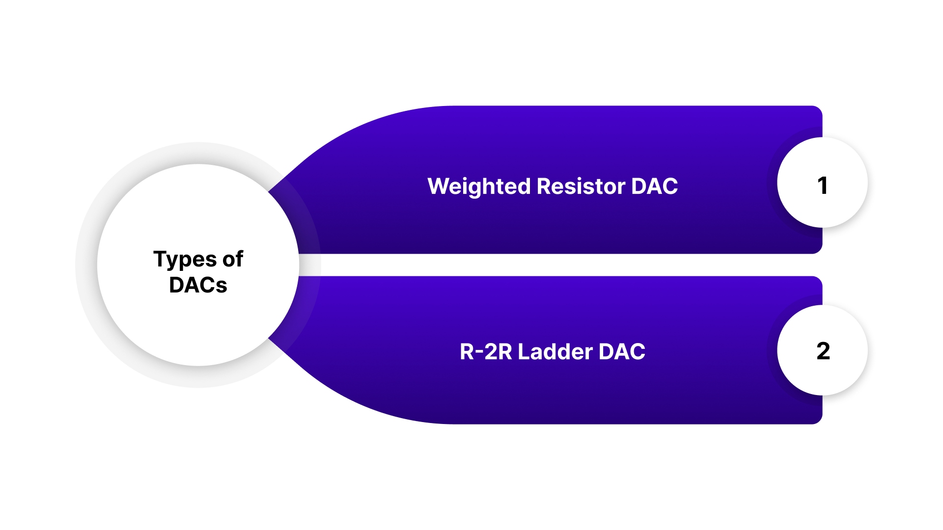
1. Weighted Resistor DAC
A Weighted Resistor DAC works by using resistors that are proportionally weighted to the binary input. The bit positions in the binary input control the connection of each resistor to a reference voltage, with the voltage at the output being a weighted sum of all active bits.
For example, consider a 3-bit binary system with input bits b2,b1,b0b_2, b_1, b_0b2,b1,b0. The resistors corresponding to each bit are weighted by powers of 2, with the most significant bit (MSB) getting the highest weight. The output voltage, based on the equation:
Drawbacks of the Weighted Resistor Method
The Weighted Resistor DAC method struggles as systems scale. Here’s why:
Exponential Growth in Resistor Values: As the number of input bits increases, resistor values grow exponentially. For high-bit systems, resistors like 1kΩ to 128kΩ are needed, making precision harder to achieve.
Accuracy Issues: Even small variations in resistor values cause errors that grow with higher bit depths, compromising the accuracy of the DAC output.
Practical Design Challenges: Sourcing precise resistors for high-bit systems is costly and complex, making it difficult to maintain consistent performance.
In essence, while this method works for low-bit DACs, it becomes impractical and error-prone as bit depth increases.
2. R-2R Ladder DAC
The R-2R Ladder DAC design addresses many of the practical shortcomings of the Weighted Resistor DAC by reducing the number of resistor values to just two: R and 2R. This simplicity makes the design far more cost-effective and scalable as the number of bits increases.
The R-2R design simplifies manufacturing by using standard resistor values, meaning you don’t need to deal with the precise resistor matching required for weighted DACs. It’s also much easier to implement and troubleshoot, especially when scaling up to 8 bits or more. The output voltage is governed by the equation:
Where Vref is the logic high voltage, and dx represents the binary digits. This system is easy to scale; adding more bits only requires adding more stages to the ladder, making it ideal for high-resolution systems.
The R-2R Ladder DAC is often the preferred choice when you need accuracy at higher bit depths without the risk of conversion errors due to resistor mismatch.
The main drawback is the requirement for high-speed op-amps (typically with a high slew rate) to accurately track fast changes in the digital input signal, especially in dynamic applications like motion control or robotics.
Now that we know about different DAC types, let's focus on the key components that make up a high-performing motion control DAC.
Key Components of a DAC
In motion control and CNC systems, Digital-to-Analog Converters (DACs) are small but crucial for achieving smooth, accurate motion. Here are the key components that ensure a motion control DAC operates effectively:
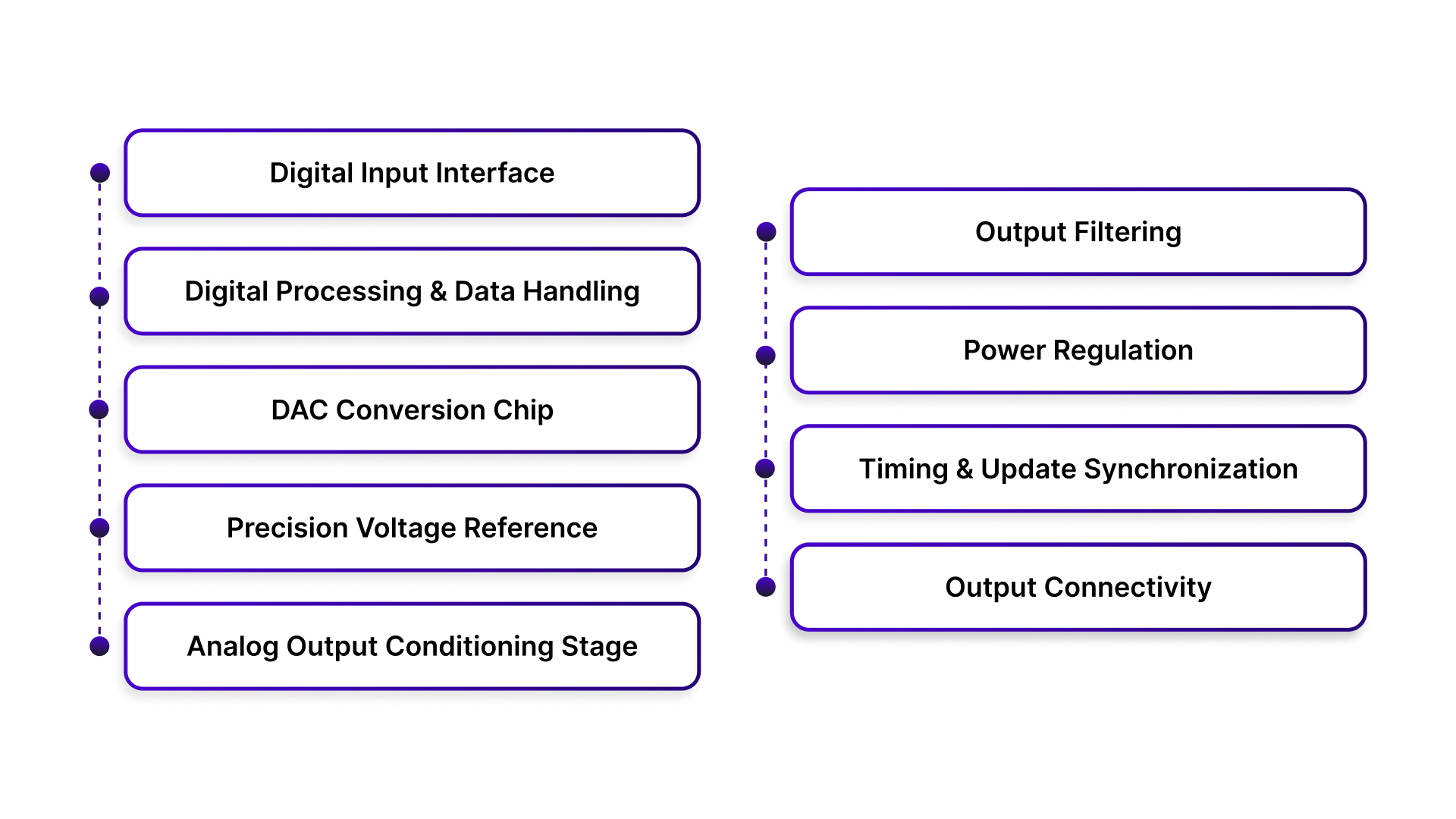
Digital Input Interface: The DAC receives digital signals from the motion controller, PLC, or CNC system, which typically represent velocity, torque, or position commands. Unlike audio DACs, motion control DACs handle control-grade data designed for real-time industrial motion.
Digital Processing & Data Handling: Before conversion, digital data undergoes processing to ensure accuracy, scaling, and synchronization with the controller’s update cycle. This step ensures that the DAC output precisely reflects the motion profile without drift or errors.
DAC Conversion Chip: The DAC chip converts digital values into analog voltage with high precision and resolution. Using technologies like resistor-ladder architectures or sigma-delta designs, the chip delivers stable, repeatable output, critical for precise motion in servo systems.
Precision Voltage Reference: A stable voltage reference is key to the DAC's accuracy. Fluctuations in reference voltage directly affect output, so ensuring a reliable reference ensures consistent analog output and stable servo responses in high-precision tasks.
Analog Output Conditioning Stage: Post-conversion, the analog signal is conditioned through amplifiers and buffers. This stage ensures the signal has the correct voltage range and drive capability to interface with servo drives, maintaining signal integrity even under industrial loads.
Output Filtering: To prevent high-frequency noise or artifacts that affect positioning accuracy, output filtering ensures a clean analog signal. This is essential for achieving vibration-free movement and precise positioning.
Power Regulation: A well-regulated power supply is crucial for consistent DAC performance. Industrial-grade DAC systems include filtering to minimize electrical noise, preventing instability that could lead to inaccurate motion.
Timing & Update Synchronization: DAC update timing is synchronized with the motion controller’s control loop, ensuring smooth and predictable changes in output signals. This synchronization is vital for maintaining real-time response in servo and CNC applications.
Output Connectivity: Industrial DACs use robust, reliable output terminals or connectors to interface with servo drives and control hardware. These connections are designed for durability, stability, and noise immunity in demanding industrial environments.
When these components work seamlessly together, a motion control DAC delivers:
Stable ±10V control signals
Smooth servo behavior
Accurate positioning and velocity control
Reliable performance in CNC, robotics, and automation
Though small, a DAC’s quality directly impacts machine precision, stability, and overall motion quality, making it essential in precision machinery and control systems.
For engineers looking to enhance their motion control systems, the Pico Systems DAC-16 offers an excellent solution. This 4-axis, 16-bit DAC is optimized for servo motion control systems, offering ±10V output and compatibility with nearly all velocity servo amplifiers.
Also Read: How to Estimate the Cost of a Production Servo Motor: A Complete Guide
With the components in mind, let's take a look at the performance specifications that make these DACs suitable for industrial use.
Digital-to-Analog Converter Performance Specifications
Several factors influence the performance of a DAC, especially in motion control and CNC applications, where precision and reliability are critical. While there are many performance specs to consider, here are a few key metrics that should be watched closely when selecting a DAC for industrial use.
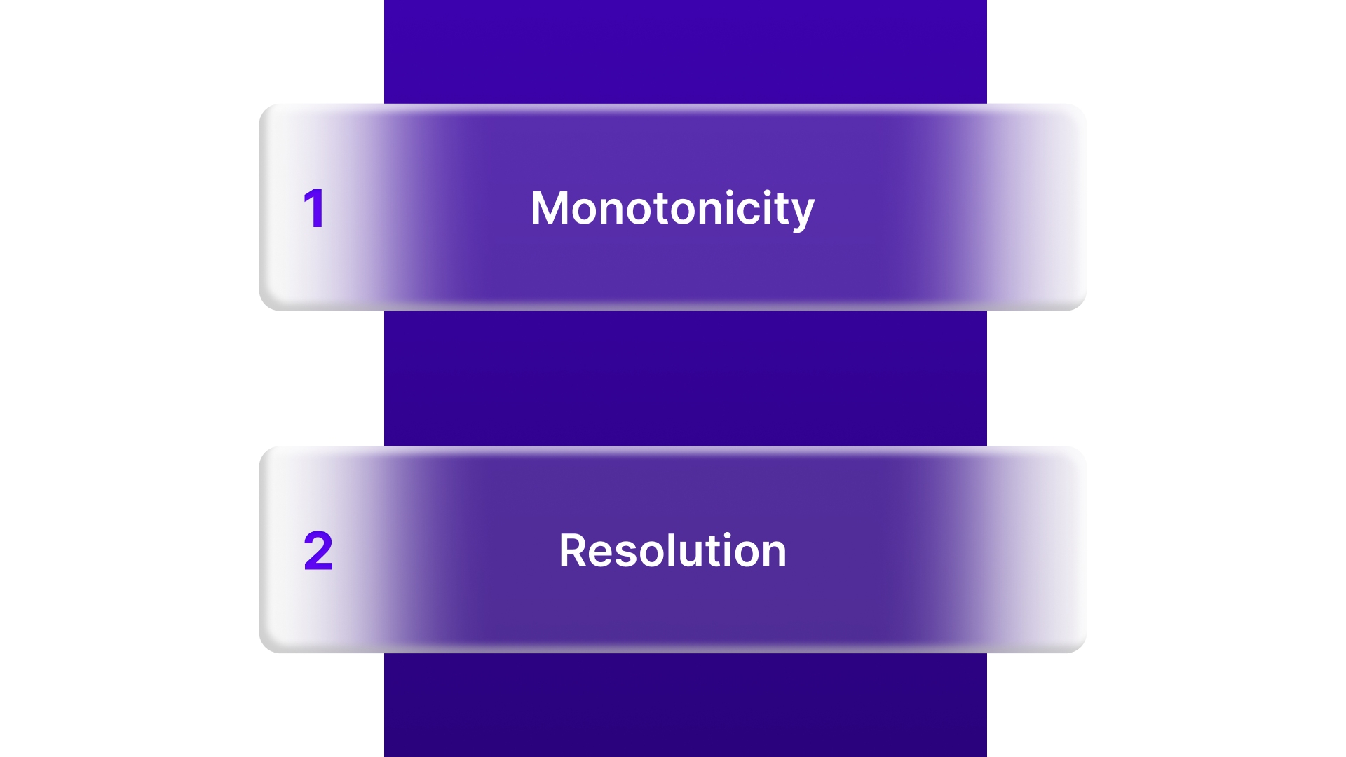
1. Monotonicity
Monotonicity in a DAC means that the output voltage increases or decreases consistently with the input code. This characteristic is essential in motion control systems, where any non-monotonic behavior would result in inaccurate control of motors or actuators.
A DAC is considered monotonic if each increase in the digital input corresponds to an increase in the output voltage, ensuring predictable and stable system behavior.
2. Resolution
The resolution of a DAC refers to the smallest change in output voltage that corresponds to the smallest change in input. This is crucial when fine control is needed for precise motion. The higher the resolution, the smaller the steps between discrete voltage levels, allowing for more accurate movement or positioning.
Resolution is typically measured in bits, which indicates how many distinct output levels the DAC can produce. The higher the number of bits, the finer the granularity of the output signal.
Resolution can be expressed in two ways:
As a percentage of the full-scale output:
Resolution=(2n−11)×100
Where n is the number of bits.As a voltage:
Resolution=VFS/2n
Where VFS is the full-scale output voltage (maximum output), and n is the number of bits.
Sometimes, you might encounter this alternate formula:
Resolution=VFS/2n -1
These specifications are crucial to ensure smooth and precise control in systems like CNC machines, robotics, and servo applications.
Conclusion
Understanding the key components and performance metrics of Digital-to-Analog Converters (DACs) is crucial for anyone involved in motion control systems. From monotonicity to resolution, each specification directly influences the precision, accuracy, and overall performance of the system.
For those looking for high-precision, reliable DAC solutions, Pico Systems offers the DAC-16 4-axis 16-bit Digital to Analog Converter. Designed specifically for servo motion control systems, this board ensures smooth and accurate velocity control with a -10V to +10V output range.
It’s optimized for use with PPMC systems, supports multiple axes, and includes essential features like watchdog logic, E-stop capabilities, and a temperature-controlled voltage reference to guarantee minimal drift. Get in touch today and ensure your system operates with precision and reliability.
FAQs
1. What does a digital-to-analog converter do?
A DAC converts digital signals into analog signals, enabling devices like motors or amplifiers to understand and respond to digital commands in systems like motion control or CNC machines.
2. Do you really need a DAC?
If your system requires digital-to-analog conversion to control physical devices like motors, then yes, a DAC is essential for smooth and accurate control.
3. Is a digital-to-analog converter worth it?
Absolutely, especially for systems where precise control is key. DACs ensure that your system can convert digital commands into analog actions, making them crucial for high-performance applications like servo control or robotics.
4. What are the disadvantages of a digital-to-analog converter?
While DACs are necessary for precision control, they can be expensive and complex. Higher resolution DACs require precise components, and noise can sometimes affect the output if not handled correctly.