The servo fault code on your HMI doesn't give you much to work with. Following error, position loss, and communication timeout. These messages tell you something is wrong, but not where to look first.
Encoders create the feedback loop that makes servo systems work. When that feedback gets corrupted or drops out entirely, your machine loses its ability to position accurately. The trick is isolating the encoder from everything else in the signal chain.
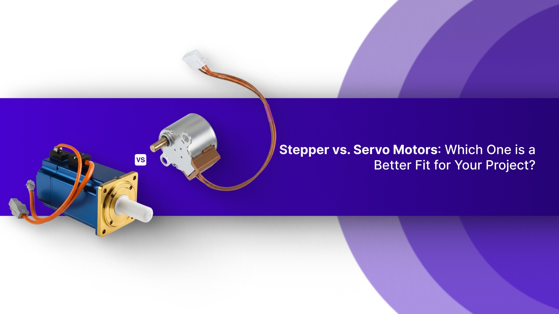
Different encoder types fail in different ways. This article walks through the main technologies you'll find in industrial servos, their typical weak points, and systematic approaches to finding the problem.
But first, let us brush up on the basics.
Key Takeaways
Incremental encoders lose position data on power loss and require homing sequences, while absolute encoders retain position information and eliminate startup delays in critical applications.
Optical encoders offer the highest resolution but fail quickly in contaminated environments, making magnetic encoders the better choice for harsh conditions despite lower accuracy.
Most encoder failures stem from environmental factors like contamination, cable degradation, and thermal drift rather than internal electronic component failure, making preventive maintenance essential.
Digital communication protocols in absolute encoders handle long cable distances better than incremental pulse signals, but require strict firmware compatibility between encoder and drive.
Linear encoders measure actual load position independently of the motor shaft, eliminating mechanical errors from ball screws and backlash that rotary encoders cannot detect.
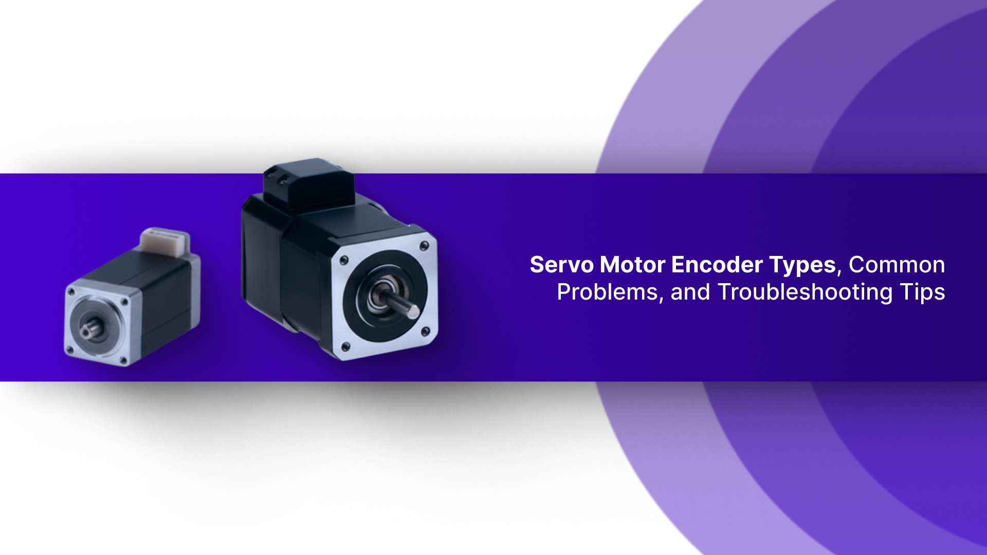
What Is a Servo Motor Encoder?
A servo motor encoder is a feedback device that converts the motor shaft's mechanical position into electrical signals. Your drive controller reads these signals to determine exactly where the rotor is and how fast it's moving.
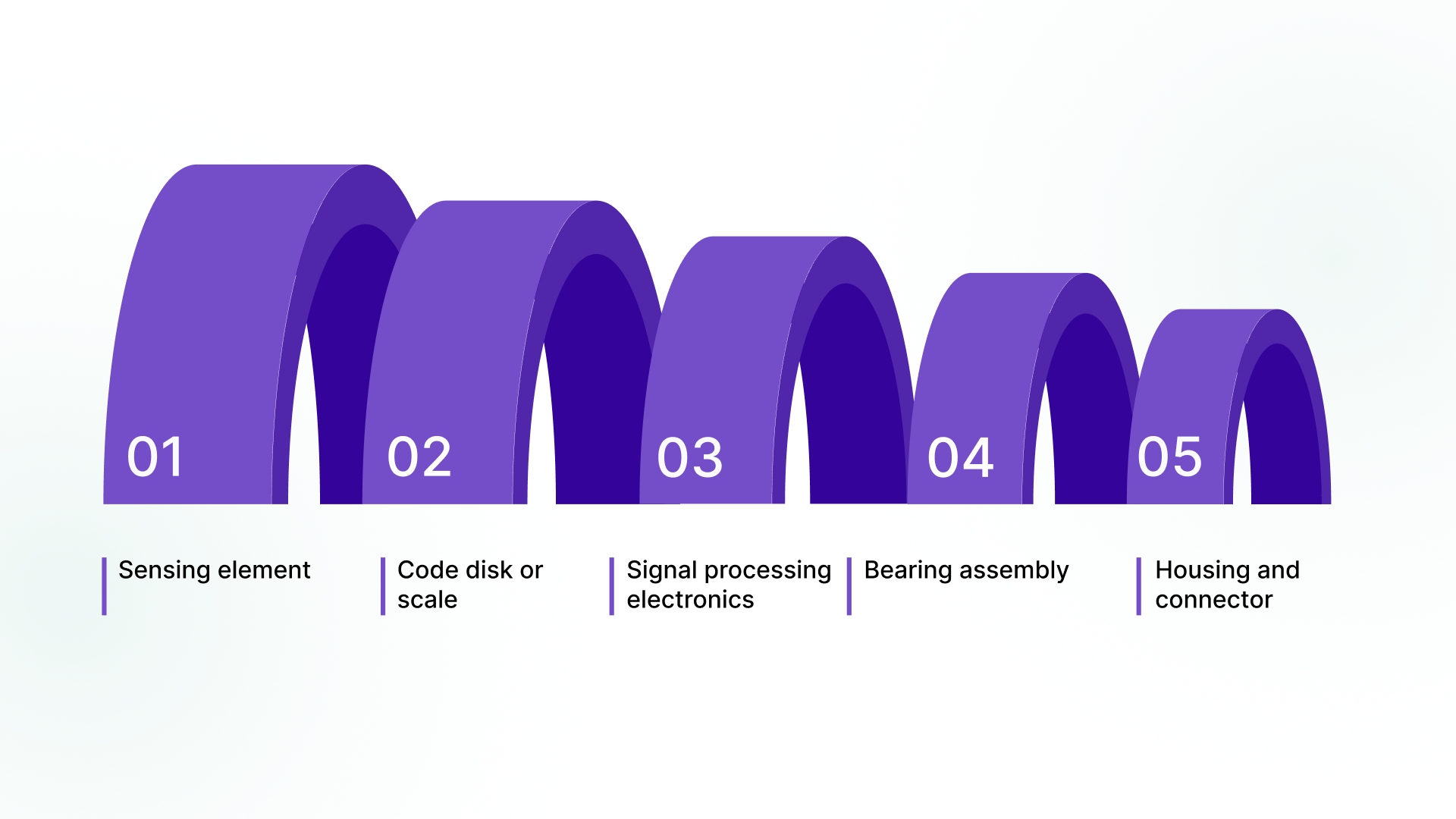
Every encoder contains a few essential components that work together to generate position data:
Sensing element – Detects shaft position through optical, magnetic, or capacitive methods.
Code disk or scale – Provides the pattern that the sensing element reads as the shaft rotates.
Signal processing electronics – Converts raw sensor data into standardized output signals.
Bearing assembly – Maintains precise alignment between the sensing element and the code disk.
Housing and connector – Protects internal components and provides an electrical interface to the drive.
These components need to maintain tight tolerances. Even small misalignments or contamination can corrupt the position signal your drive depends on.
How Does a Servo Motor Encoder Work?
The encoder tracks shaft rotation by reading a pattern on the code disk as it spins past the sensing element. Each time the pattern changes, the encoder generates a signal pulse that your drive counts.
The basic operation breaks down into these steps:
Pattern detection – The sensing element reads alternating segments on the rotating code disk.
Signal generation – Each transition from light to dark (or north to south pole) creates an electrical pulse.
Quadrature output – Two channels offset by 90 degrees
provide both position and direction information.
Pulse counting – Your drive controller counts these pulses to calculate the shaft position.
Resolution determination – More segments on the code disk mean finer position resolution.
Communication protocol – The processed signals are transmitted to the drive via incremental pulses or absolute digital data.
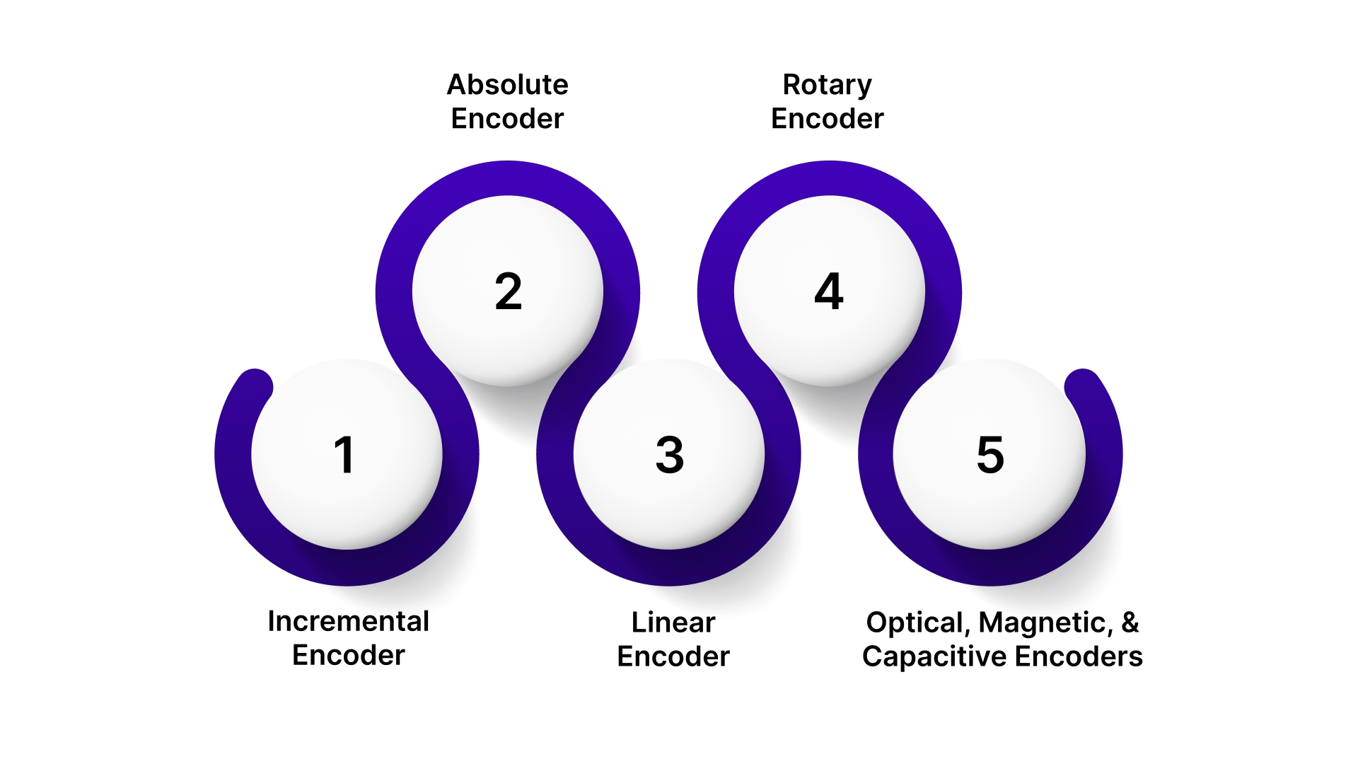
Types of Servo Motor Encoders
In this section, we will cover the main encoder types you'll encounter, their salient features, common pitfalls, and how to fix them. Let's get straight to the point.
Incremental Encoder
An incremental encoder generates pulses as the shaft rotates but doesn't retain position information when power is lost. Your drive counts these pulses from a known reference point to track position.
Key Features
Quadrature output – Two channels (A and B) offset by 90 degrees provide position and direction data
Index pulse – A single Z channel pulse per revolution establishes a home reference point
Relative positioning – Requires a homing sequence after every power cycle to establish zero position
Simple interface – Lower cost and easier integration compared to absolute encoders
High resolution available – Can achieve extremely fine position increments with optical designs
Common Problems
Loss of position on power down – System must re-home every startup, adding cycle time
Pulse counting errors – Electrical noise or signal loss causes a permanent position offset until the next homing
Cable length limitations – Analog quadrature signals degrade over long distances, typically limited to 50 meters
Bearing wear – Mechanical coupling stress can cause misalignment and signal jitter over time
Contamination sensitivity – Dust or oil on optical disks creates intermittent pulse dropouts
Troubleshooting Tips
Check signal quality with oscilloscope – Look for clean square waves with proper amplitude and 90-degree phase shift between channels
Verify cable shielding and grounding – Poor shielding allows electrical noise to corrupt pulse signals
Test index pulse consistency – Inconsistent Z pulse timing indicates mechanical or optical problems
Monitor for missed counts – Compare commanded position with feedback position during slow, controlled moves
Inspect optical disk for contamination – Clean with isopropyl alcohol and a lint-free cloth if accessible
Absolute Encoder
An absolute encoder provides unique position data for every shaft angle, retaining this information even when power is removed. Your drive knows its exact position immediately on startup without homing.
Key Features
Unique position codes – Each shaft angle has a distinct digital output value
Power-loss immunity – Position data retained without battery backup or homing routine
Multi-turn capability – Tracks total revolutions in addition to position within each revolution
Digital communication – Uses protocols like SSI, BiSS, EnDat, or EtherCAT instead of pulse trains
Reduced startup time – Eliminates homing sequences in most applications
Common Problems
Communication protocol failures – Digital bus errors cause complete position loss rather than gradual drift
Battery failure in older designs – Some multi-turn absolute encoders use batteries that eventually die
Higher replacement cost – More complex electronics make these encoders significantly more expensive
Firmware compatibility issues – Drive and encoder firmware versions must match for proper operation
Gear train wear in multi-turn types – Mechanical gear reduction for revolution counting can develop backlash
Troubleshooting Tips
Verify communication settings – Check baud rate, protocol type, and timing parameters in drive configuration
Monitor bus diagnostics – Most protocols provide error counters for CRC failures and timeout events
Test battery voltage if applicable – Replace battery before it drops below the minimum threshold
Update firmware carefully – Ensure encoder and drive firmware compatibility before updating either component
Check cable quality and termination – Digital signals require proper impedance matching and termination resistors
Linear Encoder
A linear encoder measures straight-line position instead of rotational angle, typically used on machine axes rather than motor shafts. The scale mounts along the axis of travel while the read head attaches to the moving carriage.
Key Features
Direct position measurement – Eliminates errors from ball screw pitch variation and mechanical backlash
Micron-level accuracy – Can achieve positioning accuracy below 5 microns over several meters
Thermal compensation – High-end models adjust for thermal expansion of the machine structure
Separate from motor – Measures actual load position rather than motor shaft position
Sealed or open designs – Available in protected housings for harsh environments or exposed types for clean rooms
Common Problems
Contamination on scale – Chips, coolant, or dust on the glass or steel scale can cause reading errors
Read head misalignment – Gap between read head and scale must stay within tight tolerances across the entire travel
Cable management failures – Repeated flexing of cables in cable carriers causes wire breaks
Thermal drift – Temperature changes cause expansion that creates false position readings
Shock and vibration damage – Glass scales can crack under impact, steel scales can deform
Troubleshooting Tips
Clean scale surface regularly – Use approved cleaning solutions that won't damage optical coatings
Check read head gap with feeler gauges – Verify gap stays within specification across full travel range
Inspect cables for flex fatigue – Look for cracks in the cable jacket at the cable carrier entry points
Monitor position stability at temperature – Compare readings as the machine warms up to identify thermal issues
Verify mounting rigidity – Loose scale mounting creates vibration-induced position noise
Rotary Encoder
A rotary encoder mounts directly to a rotating shaft and measures angular position. This is the standard encoder type you'll find attached to servo motors.
Key Features
Shaft or hollow-bore mounting – Either couples to the motor shaft extension or mounts over the shaft end
Compact integration – Designed to fit within the motor housing or mount on the motor rear
Standardized mounting – Uses industry-standard bolt patterns and shaft dimensions for easy replacement
Wide speed range – Operates from near-zero RPM to tens of thousands of RPM, depending on design
Environmental ratings – Available in various IP ratings for different operating conditions
Common Problems
Coupling misalignment – Flexible couplings wear out, creating radial and angular misalignment
Bearing failure – Internal encoder bearings fail from side load or contamination ingress
Shaft seal degradation – Worn seals allow moisture and contamination into the encoder housing
Vibration transmission – Motor vibration transfers through rigid coupling and damages encoder internals
Electrical connector issues – Loose pins or corroded contacts can cause intermittent signal loss
Troubleshooting Tips
Check coupling condition – Replace worn flexible couplings that show cracking or set screw damage
Measure shaft runout – Excessive runout indicates bearing problems or bent shaft
Test seal integrity – Look for moisture or contamination inside encoder housing during inspection
Verify mounting hardware torque – Loose mounting bolts allow encoder to shift and create alignment problems
Inspect connector pins – Check for bent pins, corrosion, or loose retention in housing
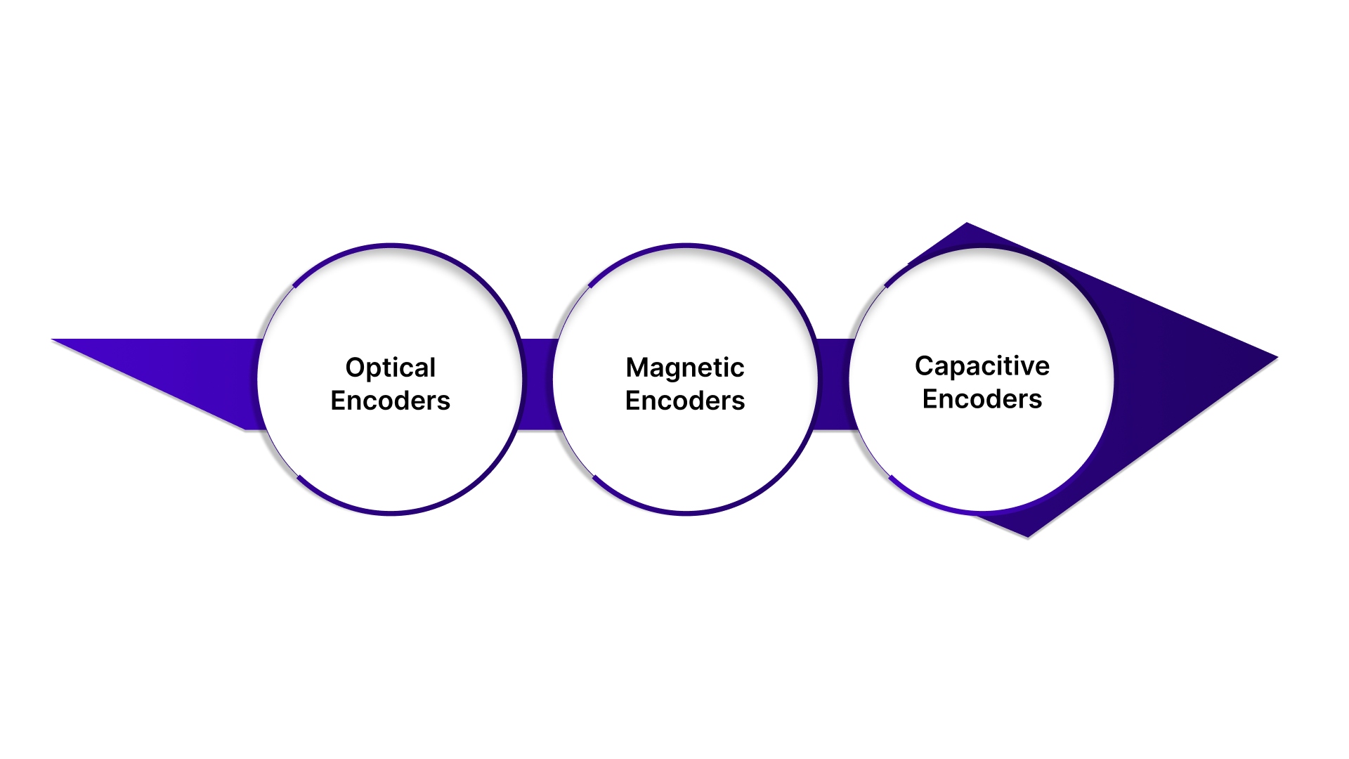
Optical, Magnetic, and Capacitive Encoders
These three sensing technologies represent different methods of detecting shaft position, each with distinct advantages and vulnerabilities.
A. Optical Encoders
Optical encoders use LED light passing through a patterned code disk to photodetectors. This remains the most common technology for high-resolution applications.
Key characteristics:
Highest resolution available – Can achieve millions of counts per revolution with fine optical patterns
Excellent accuracy – Precise photolithography creates consistent patterns with minimal error
Contamination sensitive – Dust or oil on the glass disk blocks light and creates signal dropouts
Temperature stable – Minimal drift over wide temperature ranges compared to magnetic types
Requires a clean environment – Best suited for enclosed motors or clean manufacturing areas
Common problems and fixes:
Contamination on the code disk – Clean the disk with isopropyl alcohol if encoder design allows access
LED degradation over time – Replace encoder when light output drops below detection threshold
Photodetector failure – Usually requires complete encoder replacement as components aren't serviceable
Condensation formation – Ensure proper sealing and avoid rapid temperature changes that cause moisture buildup
B. Magnetic Encoders
Magnetic encoders detect alternating magnetic poles on a rotating ring or drum. These designs handle harsh environments better than optical types.
Key characteristics:
Robust against contamination – Oil, dust, and moisture don't affect magnetic field detection
Lower resolution ceiling – Typically limited to thousands rather than millions of counts per revolution
Temperature sensitivity – Magnetic field strength changes with temperature, affecting signal amplitude
Shock and vibration resistant – No delicate optical components to damage under impact
Good for harsh environments – Ideal for food processing, washdown applications, and outdoor use
Common problems and fixes:
Magnetic ring demagnetization – Exposure to strong external magnetic fields corrupts pole pattern permanently
Temperature-induced drift – Calibrate the system at the operating temperature or use temperature compensation
Hall sensor failure – Replace encoder as individual sensors typically aren't field-serviceable
Ferrous contamination buildup – Metal particles attracted to the magnetic ring interfere with field patterns; clean regularly
C. Capacitive Encoders
Capacitive encoders measure changes in capacitance between the sensor plates and a patterned rotor. This technology is less common but offers unique benefits.
Key characteristics:
Immune to light and magnetism – Works in environments where optical or magnetic methods fail
Moderate resolution – Falls between magnetic and optical types in achievable resolution
Humidity sensitivity – Moisture changes dielectric properties and affects capacitance readings
Wear-resistant – Non-contact design with no light sources to degrade over time
Compact implementation – Can be integrated into very small form factors
Common problems and fixes:
Humidity-induced errors – Use conformal coating on electronics or specify sealed designs for humid environments
Contamination on rotor plates – Conductive contamination creates electrical bridging between sensor elements
Electronic drift – Recalibrate zero offset periodically as capacitive sensing circuits age
Grounding issues – Ensure proper shielding and grounding to prevent external electrical interference
At Pico Systems, we offer top-quality encoder solutions that bridge the gap between proprietary and industry-standard signals. Our products, like the Fanuc Serial Encoder Converter and Panasonic Encoder Converter, are designed for seamless integration with most brushless drives.
Shop for our advanced encoder products
and enhance your motion control systems today.
How to Choose the Right Servo Motor Encoder for Your Specific Application
We are not going to tell you the obvious, that resolution and accuracy matter. Instead, we will guide you through the practical considerations that impact your machine's performance and reliability.
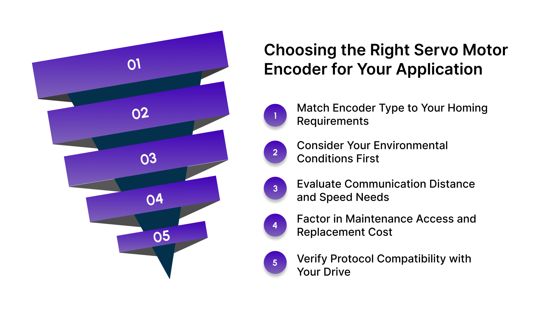
Match Encoder Type to Your Homing Requirements
If your application can tolerate a homing sequence at every startup, incremental encoders cost less and offer higher resolution. For machines that need instant position awareness after a power loss, absolute encoders eliminate downtime from homing routines.
Consider Your Environmental Conditions First
Optical encoders deliver the best resolution in clean environments but fail quickly when exposed to coolant or metal chips.
Magnetic encoders survive harsh conditions but sacrifice some accuracy. Match the sensing technology to your actual operating environment, not ideal conditions.
Evaluate Communication Distance and Speed Needs
Incremental pulse signals degrade over long cable runs, causing count errors that corrupt your position data. Absolute encoders with digital protocols handle extended distances reliably but require compatible drive hardware. Choose based on your physical layout and how far the encoder sits from your controller.
Factor in Maintenance Access and Replacement Cost
Encoders mounted inside sealed motor housings require complete motor removal for service. External encoders with accessible mounting allow quick replacement but need protection from impacts. Balance the initial cost savings against the labor expense of future encoder failures.
Verify Protocol Compatibility with Your Drive
Not every absolute encoder protocol works with every servo drive. SSI, BiSS, EnDat, and Hiperface all require specific drive support.
Check compatibility before specifying an encoder, because mismatched protocols mean the system simply will not function, regardless of other specifications.
Account for Speed Range and Dynamic Response
High-speed spindle applications stress encoder bearings and signal processing electronics differently than slow positioning axes. Verify the encoder's maximum RPM rating includes a safety margin above your peak speed.
Inadequate dynamic response causes following errors during rapid acceleration and deceleration.
Conclusion
Encoder failures will happen eventually, but understanding the technology in your servos changes how quickly you recover. The difference between hours of diagnostic guesswork and targeted troubleshooting comes down to knowing what can fail and where to look first.
Environmental factors, signal integrity, and mechanical alignment cause most problems you'll encounter in the field. Using knowledge, you can keep your motion control systems running with minimal interruption.
Pico Systems is a trusted supplier of encoder converters and encoder counters from major manufacturers, so you're not forced into complete assembly replacements. We also offer CNC motion control hardware for PCs.
Our technical team understands motion control integration and helps you identify the exact part your application requires.
Connect with us today to source the encoder components your system needs and get back to production faster.
Frequently Asked Questions
What is a servo motor encoder used for?
A servo motor encoder converts the motor shaft's mechanical position into electrical signals that your drive controller reads to maintain precise positioning and speed control in closed-loop servo systems.
What happens when a servo motor encoder fails?
You'll see following errors, position loss, erratic motion, or complete communication failure. The servo drive loses feedback data and cannot maintain accurate positioning until the encoder is repaired or replaced.
Can I replace an incremental encoder with an absolute encoder?
Not directly. Absolute encoders use different communication protocols and wiring than incremental types. Your drive must support the absolute encoder's specific protocol like SSI, BiSS, or EnDat for proper operation.
How do I know if my servo motor encoder is bad?
Check for intermittent position errors, inconsistent homing, signal dropouts on an oscilloscope, or physical damage like bearing noise and contamination on the code disk or sensing elements.
What's the difference between optical and magnetic servo motor encoders?
Optical encoders use light and achieve higher resolution but require clean environments. Magnetic encoders detect magnetic poles, offer lower resolution, but survive contamination, moisture, and harsh industrial conditions better.
.