Every CNC system needs a motor driver board. It's the component that bridges your motion controller to your stepper or servo motors by converting logic-level signals into the power pulses that the motors understand.
You're probably familiar with the basics, but the devil lives in the details. Current ratings, microstepping capabilities, thermal management - these factors determine whether your machine runs smoothly or stalls mid-cut.
Today, we will explore what driver boards do under the hood, which features count for industrial applications, and how to select hardware that matches your performance requirements.
Key Takeaways
CNC motor driver boards convert digital signals into precise motor movements, ensuring accurate execution of machine commands.
Proper components such as power MOSFETs, current-sensing resistors, and protection circuitry are essential for stable performance.
Selecting the right driver depends on matching it to the motor type (stepper vs. servo) and considering performance needs such as speed and torque.
Overheating, motor stalling, and electrical noise are common issues with motor drivers that can be mitigated with correct setup and cooling.
Compatibility with the motion controller and power supply is critical for avoiding underperformance and ensuring smooth operation.
What Is a CNC Motor Driver Board?
A CNC motor driver board contains circuitry that connects the motion controller to the motors (stepper or servo). It converts digital signals from the controller into electrical pulses that control motor movement.
This ensures precise control and accurate execution of commands. Without the motor driver board, the motor wouldn't respond to the controller's instructions, causing the machine to malfunction.
Key Components of a CNC Motor Driver Board
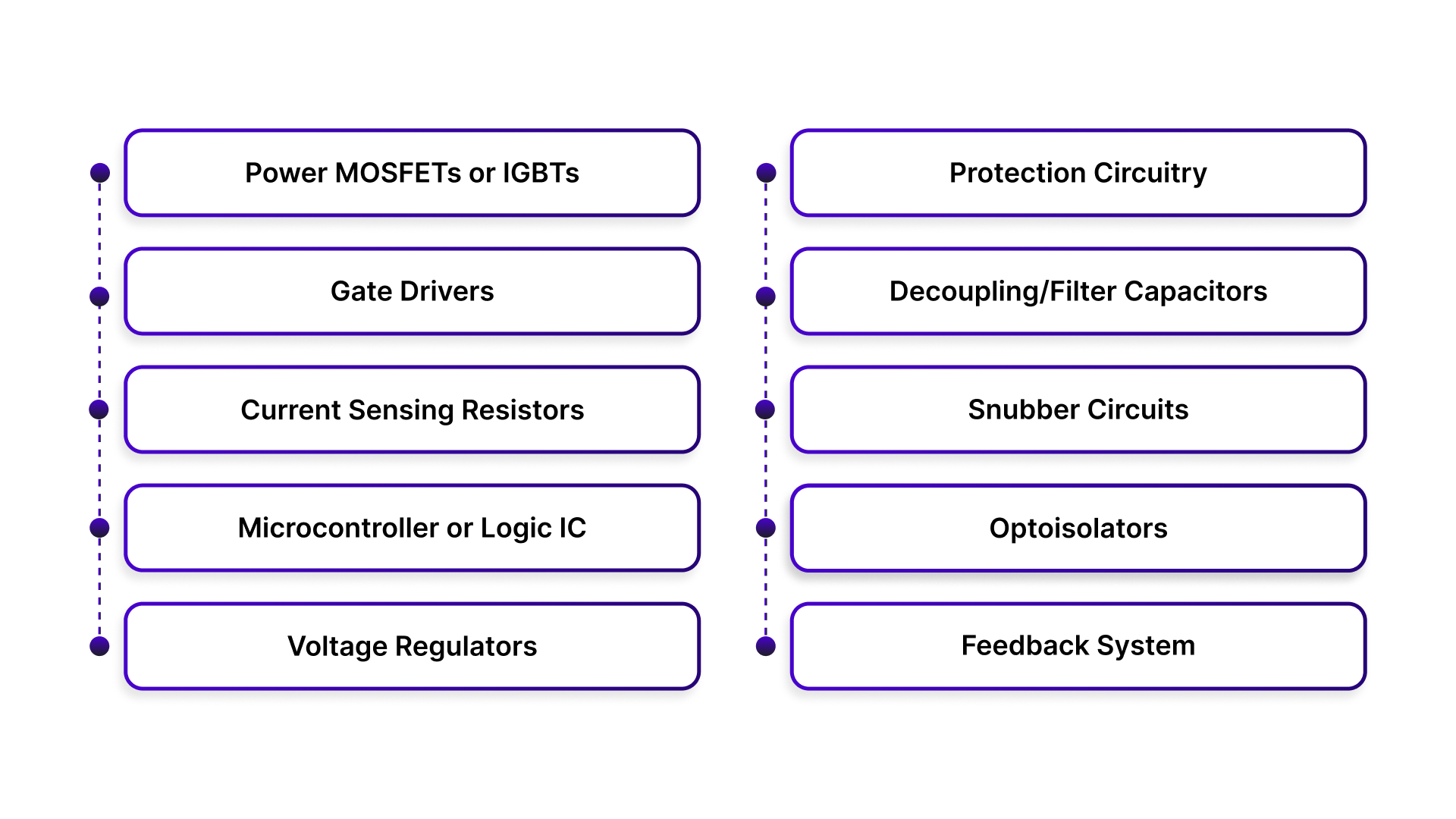
Every driver board is built around a few essential pieces that work together:
Power MOSFETs or IGBTs - These switching transistors handle the heavy current flow to the motor windings. They turn on and off thousands of times per second to create the stepping sequence.
Gate Drivers - These circuits control the MOSFETs by providing the precise voltage needed to switch them cleanly. Poor gate drive leads to slow switching and heat buildup.
Current Sensing Resistors - Tiny precision resistors that monitor how much current flows through each motor phase. This feedback lets the driver regulate torque and prevent overcurrent damage.
Microcontroller or Logic IC - The brain of the driver that interprets incoming step/direction signals and orchestrates the switching sequence. More advanced drivers include built-in motion profiles and protection features.
Voltage Regulators - Step down the main power supply to run the logic circuits and gate drivers. Keeps the control side isolated from the noisy motor power.
Protection Circuitry - Includes overcurrent detection, thermal shutdown, and short circuit protection to keep your system safe when things go wrong.
Decoupling/Filter Capacitors - Handle voltage spikes and smooth out power delivery. Critical for stable operation and protecting MOSFETs from voltage transients.
Snubber Circuits - Dampen electrical noise and voltage spikes generated during switching. Helps with EMI and extends component life.
Optoisolators - Provide electrical isolation between the low-voltage control signals and high-voltage motor circuits. Common in industrial applications for noise immunity and safety.
Feedback System (Optional) - Some systems use encoders or sensors for real-time motor position feedback, improving accuracy.
How Does a CNC Motor Driver Board Work?
The process starts when the motion controller sends a step pulse. Each pulse tells the driver to advance the motor by one increment. A separate direction signal tells the driver which way to rotate.
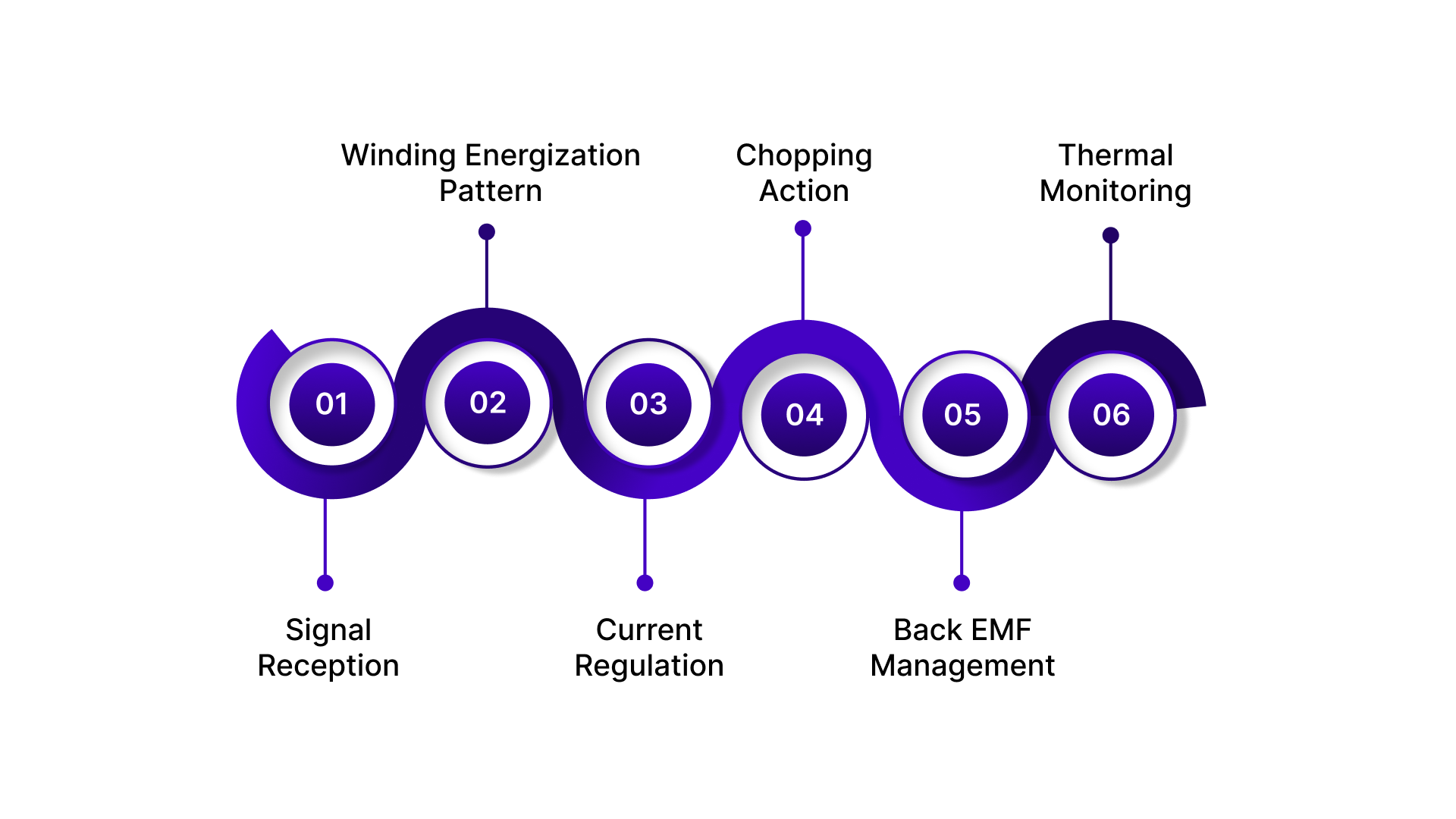
Here's what happens inside the driver board during each step cycle:
Signal Reception - The logic IC or microcontroller receives the step and direction signals. It decodes these into a specific firing sequence for the motor windings.
Winding Energization Pattern - For a stepper motor, the driver energizes the coils in a precise sequence. Full step mode energizes one or two phases at a time. Microstepping modes blend the current between phases to create intermediate positions.
Current Regulation - The driver uses pulse width modulation (PWM) to control current flow. It rapidly switches the MOSFETs on and off, adjusting the duty cycle to maintain the target current level set by the current sensing resistors.
Chopping Action - When the current reaches the set point, the driver chops the voltage by turning off the MOSFETs. Current recirculates through freewheeling diodes. When the current drops below the threshold, the MOSFETs turn back on. This chopping happens thousands of times per second.
Back EMF Management - As the motor spins, it generates back electromotive force that opposes the applied voltage. The driver compensates by adjusting the PWM duty cycle to maintain consistent torque across the speed range.
Thermal Monitoring - Temperature sensors on the board track heat buildup. If temperatures exceed safe limits, the protection circuitry reduces current or shuts down completely to prevent component damage.
The entire sequence repeats for every step pulse. At high step rates, this means the driver is making decisions and switching power transistors tens of thousands of times per second while maintaining precise current control in each motor phase.
Selecting the Right CNC Motor Driver Board for Your Application
Picking the wrong driver means dealing with poor performance or outright failure. The right match depends on the motor type, the application demands, and how everything connects together.
Match the Driver to the Motor Type
Stepper and servo motors need different driving strategies.
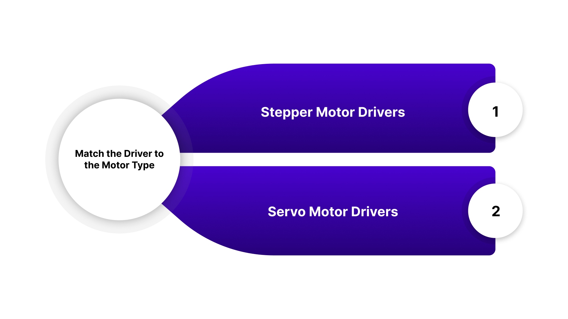
Stepper Motor Drivers work with bipolar or unipolar stepper motors. They control current in phases to create discrete steps. Look for microstepping capability if smooth motion is needed. Common configurations are 2-phase for NEMA steppers.
Servo Motor Drivers require different control signals. They work with encoder feedback for closed-loop positioning. These drivers handle higher speeds and dynamic loads better than stepper drivers.
Some use analog command signals, others take digital pulse trains. NEMA servo motors combine the mounting compatibility of stepper motors with servo performance and typically work with standard servo drivers.
Using a stepper driver on a servo motor won't work. They speak different languages.
For both stepper and servo motors, Pico Systems offers the Universal Stepper Controller. This 4-axis controller seamlessly handles both motor types, offering precise control with smoother step pulses and the ability to integrate encoders for accurate position tracking.
It also includes an E-stop controller and extra digital inputs for additional switches and relays, making it ideal for a range of CNC setups.
Want to simplify your CNC control system? Check out Pico Systems' entire product line here.
Matching Hardware to Performance Needs
Consider the following specific performance requirements of your CNC application:
High-Speed Applications: Choose drivers that can handle rapid motor switching and fast response times.
High-Torque Applications: Ensure the driver supports sufficient current and voltage for heavy loads.
Precision Tasks: Select drivers with microstepping capabilities to provide smoother motor movement and finer resolution.
Other Considerations
Compatibility with Motion Controller: Ensure the driver board is compatible with your CNC motion controller, whether it’s a standalone controller or part of a larger system.
Power Supply: Verify that the driver board is matched to the motor’s voltage and current requirements to avoid overloading or underperformance.
Common Issues With CNC Motor Driver Boards and Troubleshooting Tips
Even properly selected drivers can run into problems during operation. Most issues trace back to thermal management, electrical noise, or incorrect configuration settings.
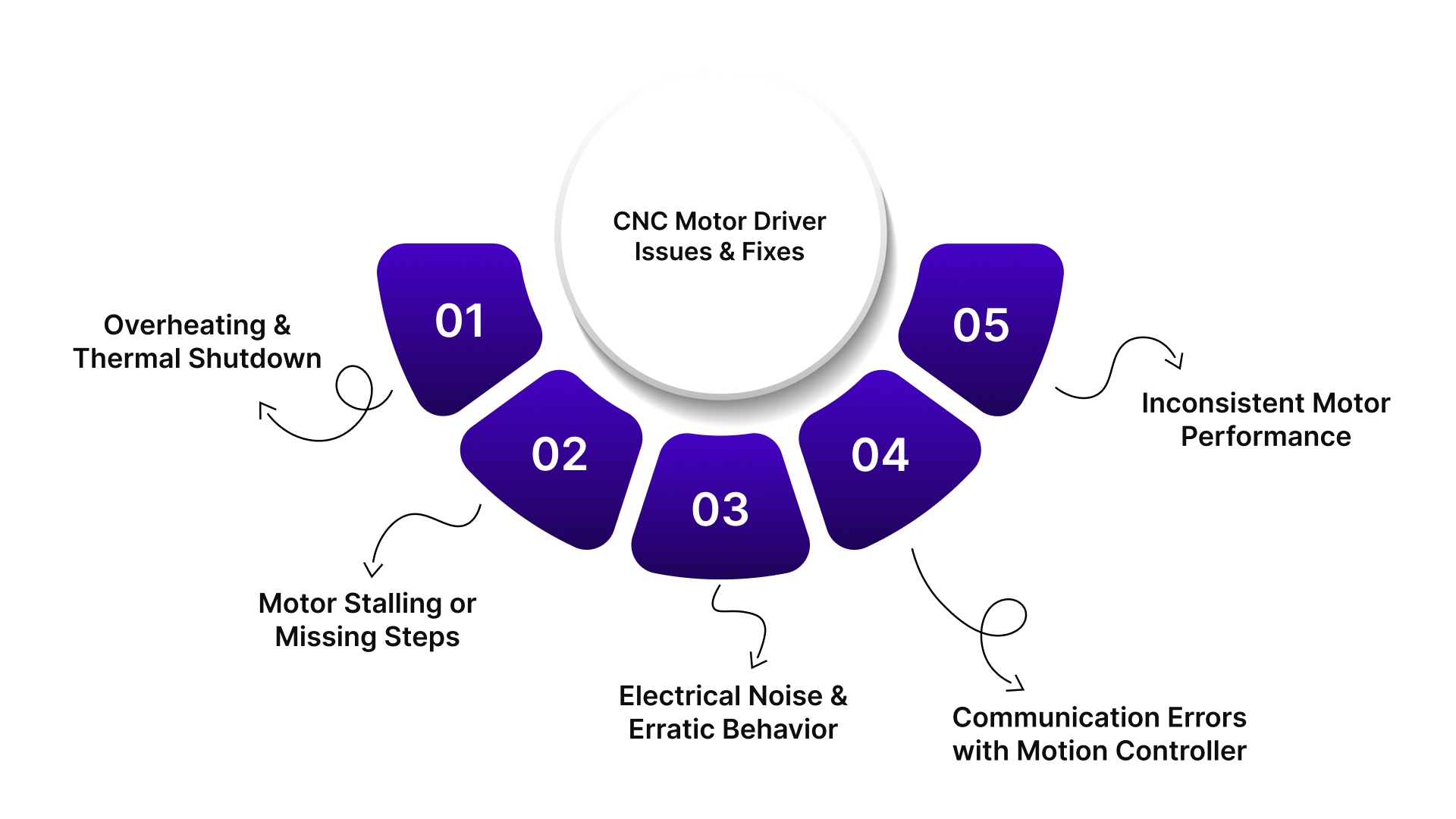
Overheating and Thermal Shutdown
Issue: The driver board shuts down intermittently or reduces motor current during operation. Surface temperatures exceed safe limits and trigger thermal protection circuits.
Solution:
Verify the heatsink is properly attached with thermal compound
Add active cooling with fans if ambient temperature is high
Reduce motor current settings if full torque isn't needed
Check for adequate airflow around the driver enclosure
Ensure the driver isn't mounted near other heat-generating components
Motor Stalling or Missing Steps
Issue: The motor fails to complete moves or loses position during acceleration. Steps are skipped under load or at higher speeds.
Solution:
Increase the current limit setting to provide more torque
Reduce acceleration rates in the motion controller
Check for mechanical binding or excessive load on the motor
Verify the power supply voltage is adequate for the speed range
Lower microstepping resolution to increase available torque
Electrical Noise and Erratic Behavior
Issue: The driver responds to phantom step pulses or resets randomly. Control signals are corrupted by electromagnetic interference from motor cables or other equipment.
Solution:
Use shielded cables for motor connections and ground the shields at one end
Separate motor power cables from control signal wires
Add ferrite beads or common-mode chokes on motor leads
Verify proper grounding between the controller, driver, and power supply
Enable input filtering or debounce settings if available on the driver
Communication Errors with Motion Controller
Issue: The driver doesn't respond to commands or reports connection failures. Step pulses aren't recognized, or direction changes are ignored.
Solution:
Check signal voltage levels match between the controller and the driver
Verify the pinout and wiring of the step, direction, and enable signals
Add pull-up or pull-down resistors if inputs are floating
Reduce the cable length between the controller and the driver
Enable opto-isolation if electrical noise is present
Inconsistent Motor Performance
Issue: The motor runs smoothly sometimes but exhibits vibration, noise, or rough movement at certain speeds. Resonance causes loss of torque in specific RPM ranges.
Solution:
Enable anti-resonance or damping features in the driver settings
Adjust microstepping resolution to shift resonant frequencies
Use a higher supply voltage to improve damping at mid-range speeds
Add mechanical damping or change the load inertia ratio
Try different current decay modes (fast, slow, mixed) in the driver configuration
Conclusion
Motor driver boards are the critical link between control electronics and physical motion in CNC systems.
Getting the selection right means matching electrical specifications to motor requirements, ensuring thermal headroom for continuous operation, and verifying signal compatibility across the entire motion chain.
When problems arise, most trace back to heat, noise, or configuration rather than component failure.
At Pico Systems, we design interfaces that bridge the gap between controllers and drive systems. Our Gecko Interface connects Gecko 320-series servo drives to the Universal Stepper Controller, handling encoder feedback, E-stop logic, and fault management in one compact package.
Browse our complete product range to find components that fit your specific needs.
FAQs
1. What is a CNC motor driver board?
A CNC motor driver board converts digital signals from the controller into electrical pulses, controlling motor movement with precision for accurate CNC machine operation.
2. How does a CNC motor driver board work?
It receives step and direction signals from the motion controller, energizes the motor coils in a specific sequence, and manages current flow for smooth motor control.
3. What are common issues with CNC motor driver boards?
Common issues include overheating, motor stalling, electrical noise, communication errors, and inconsistent motor performance, all of which can be addressed with proper setup and troubleshooting.
4. How do I select the right CNC motor driver board?
Match the driver to the motor type (stepper or servo), consider your application's speed, torque, and precision needs, and ensure compatibility with your motion controller and power supply.
5. Can I use the same motor driver for stepper and servo motors?
No, stepper and servo motors require different drivers due to their control signals and feedback systems. Using the wrong driver can lead to performance issues.