Motors don’t respond to voltage alone; they respond to timing. How precisely that timing is controlled determines whether a motor runs smoothly, overheats, stalls, or delivers repeatable performance under load.
That timing is defined by a PWM motor controller.
PWM (Pulse Width Modulation) allows you to control motor speed, torque, and power delivery by switching signals on and off at controlled intervals. It’s the foundation behind everything from small DC motors to industrial servo systems. But not all PWM implementations behave the same. Software-generated signals drift. Poor timing introduces noise. Inadequate power handling creates instability.
Core takeaways
A PWM motor controller regulates motor speed and torque by controlling duty cycle and frequency.
Microcontroller PWM works for simple use cases but has timing and reliability limits.
Hardware PWM systems deliver deterministic signals without CPU dependence.
Encoder feedback, braking, and thermal control are critical in industrial setups.
Pico Systems offers complete PWM servo solutions designed for LinuxCNC and industrial motion control.
What Is a PWM Motor Controller?
A PWM motor controller regulates motor speed and torque by controlling how long power is applied to the motor rather than reducing the supply voltage itself.
PWM (Pulse Width Modulation) works by switching the motor’s supply voltage ON and OFF at a high frequency. The ratio of ON time to total cycle time, known as the duty cycle, determines the effective power delivered to the motor.
Instead of wasting energy as heat (as in linear voltage control), a PWM motor controller delivers full voltage pulses, making it highly efficient and ideal for industrial, robotic, and automation systems.
For example, a 50% duty cycle on a 12V supply produces an average motor response similar to 6V, while still applying full voltage during each pulse. The motor’s inductance smooths these pulses, resulting in stable torque and speed.
How PWM Controls Motor Behavior
In motor control applications, PWM directly influences:
Speed by adjusting the duty cycle
Torque by controlling average current through the windings
Efficiency by minimizing power loss in the controller
The switching frequency also plays a key role. Higher frequencies reduce current ripple and audible noise but increase switching losses in the power electronics. Most DC motor PWM controllers operate between 1 kHz and 20 kHz, balancing smooth motion and thermal efficiency.
Core PWM Signal Characteristics
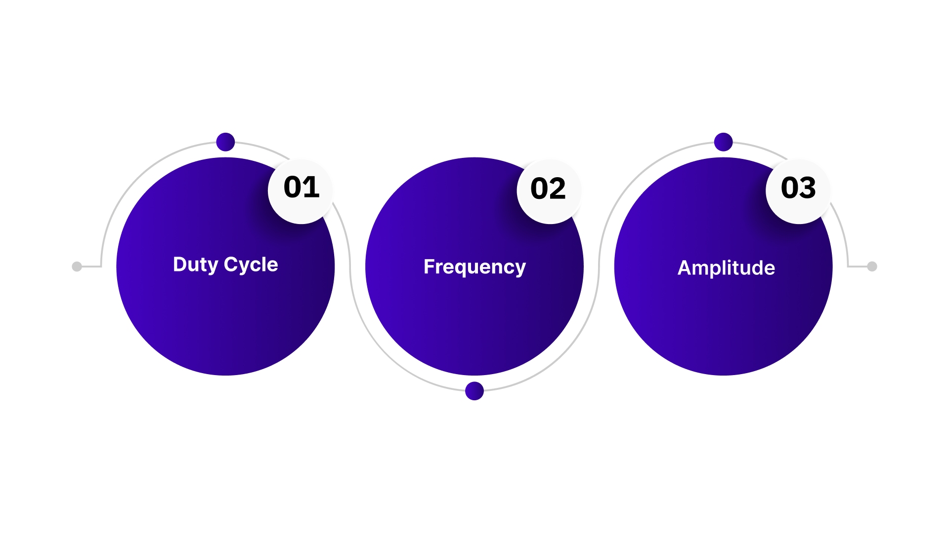
A PWM signal is defined by three parameters:
1. Duty Cycle
Controls how long the signal stays HIGH in each cycle.
0% → Motor off
50% → Reduced speed / torque
100% → Full speed
2. Frequency
Defines how fast the signal switches ON and OFF.
Typical range: 1 kHz–20 kHz
Higher frequency = smoother motor operation
3. Amplitude
The voltage level when the signal is HIGH.
Matches the motor’s rated voltage (5V, 12V, 24V, etc.)
PWM Implementation in Motor Controllers
Modern pwm motor controllers use power electronics to translate control signals into high-current motor drive signals. Common implementations include:
Hard-switched PWM using MOSFETs or IGBTs
Resonant PWM to reduce switching losses
Advanced PWM methods in closed-loop systems where duty cycles adjust dynamically based on current or encoder feedback
In industrial systems, PWM is rarely used alone. It operates as part of a closed-loop motion control system, enabling accurate torque, speed, and position control under changing load conditions.
Core Hardware Components for a PWM Motor Controller
A reliable PWM motor controller depends on carefully selected hardware that delivers stable switching, accurate control, and long-term durability. Each component plays a direct role in efficiency, responsiveness, and protection.
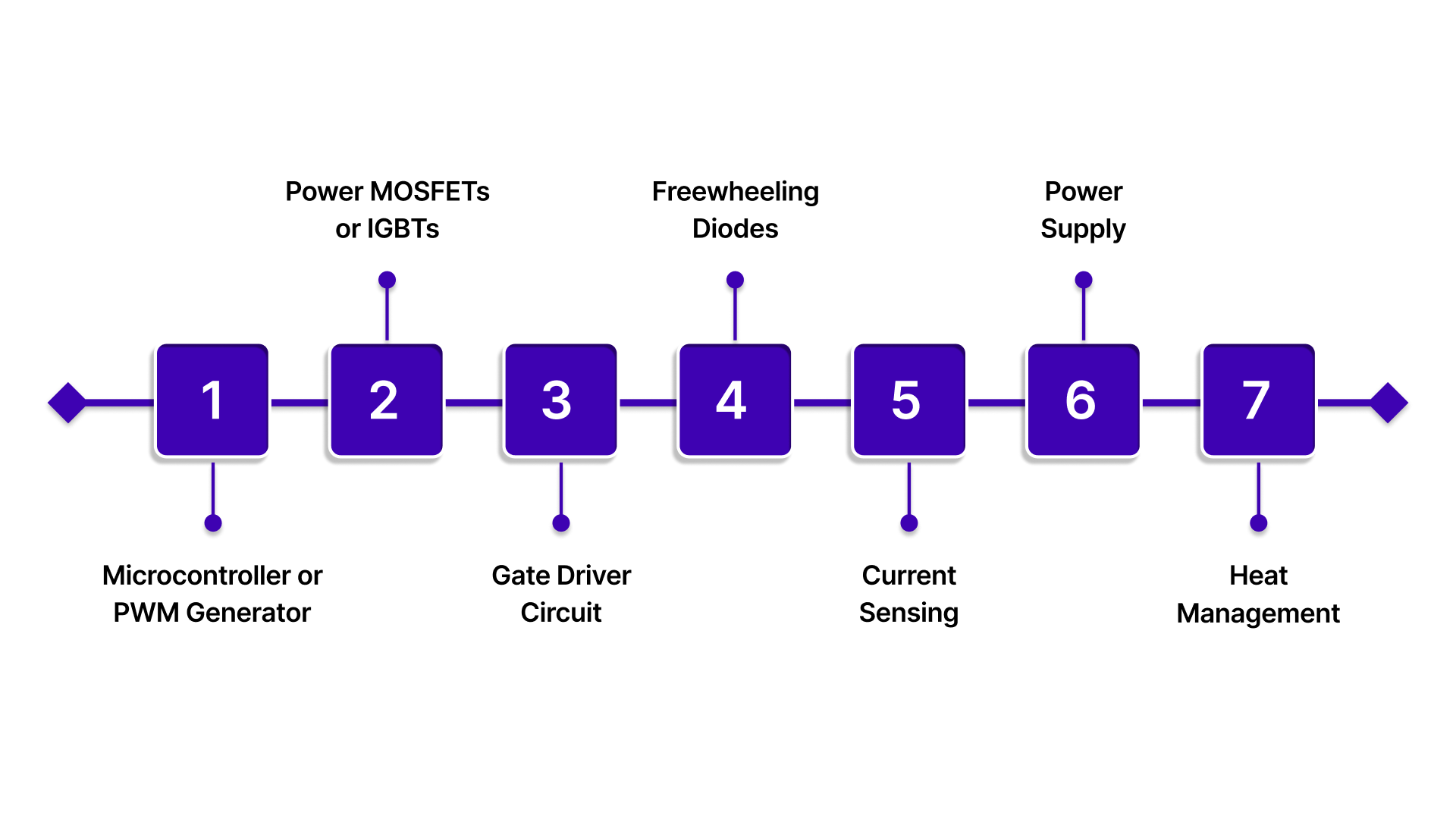
Microcontroller or PWM Generator
The controller generates the PWM signal that defines motor speed and torque. This can be a microcontroller with built-in PWM peripherals (STM32, PIC, Arduino) or a dedicated PWM IC such as TL494 or SG3525.
Key considerations:
PWM resolution: 8-bit or higher for smoother speed control
Frequency range: Typically 1–20 kHz to balance switching losses and audible noise
Drive capability: Must reliably control the switching stage
Power MOSFETs or IGBTs
The switching device handles motor current and converts PWM signals into controlled power delivery. N-channel MOSFETs are common for low- to medium-voltage systems, while IGBTs suit higher-power applications.
Critical parameters:
Voltage rating: At least 20–30% above supply voltage
Current rating: Must handle peak motor current with margin
Switching performance: Lower gate charge improves efficiency
Gate Driver Circuit
Gate drivers ensure fast, clean switching of MOSFETs, reducing heat and improving efficiency. Dedicated drivers such as IR2110 or TC4427 provide the required current to charge and discharge the gate capacitance quickly.
Key features:
High peak output current for rapid transitions
Support for high-side or low-side switching
Freewheeling Diodes
Motors are inductive loads. Fast-recovery or Schottky diodes provide a safe path for current during PWM turn-off, protecting the switching devices from voltage spikes.
Current Sensing
Current feedback improves protection and control accuracy. Low-value shunt resistors combined with current-sense amplifiers allow real-time monitoring for overload detection and closed-loop regulation.
Power Supply
A stable, low-noise DC supply is essential for consistent PWM operation. Adequate current capacity and local bulk capacitance near the motor help manage transient loads and voltage dips.
Heat Management
Switching losses generate heat that must be controlled. Proper heatsinks, airflow, and temperature monitoring ensure the pwm motor controller operates reliably under continuous load.
Software-generated PWM can work for basic motor control, but industrial environments expose its limits quickly. Timing jitter, missed pulses, and unreliable shutdowns turn into vibration, thermal stress, and positioning errors.
Pico Systems addresses this by shifting PWM generation and motor drive control into dedicated hardware. With brush and brushless PWM servo amplifiers, encoder converters for Fanuc and Panasonic motors, and integrated braking and power management, Pico Systems transforms PWM from a control signal into a dependable motion platform.
Microcontroller-Based PWM Generation
Most modern PWM motor controller designs rely on microcontrollers to generate stable, high-resolution PWM signals using dedicated hardware peripherals. Instead of relying on software loops, timers and compare units handle PWM generation directly, ensuring precise duty cycle and frequency control without CPU overhead.
This hardware-driven approach delivers consistent switching, predictable timing, and reliable motor response, critical for motion control, robotics, and automation systems.
Timer Modules and PWM Modes
Microcontrollers generate PWM by incrementing a timer at a fixed clock rate and comparing it against a programmed value. When the timer reaches the compare value, the output state changes, defining the duty cycle.
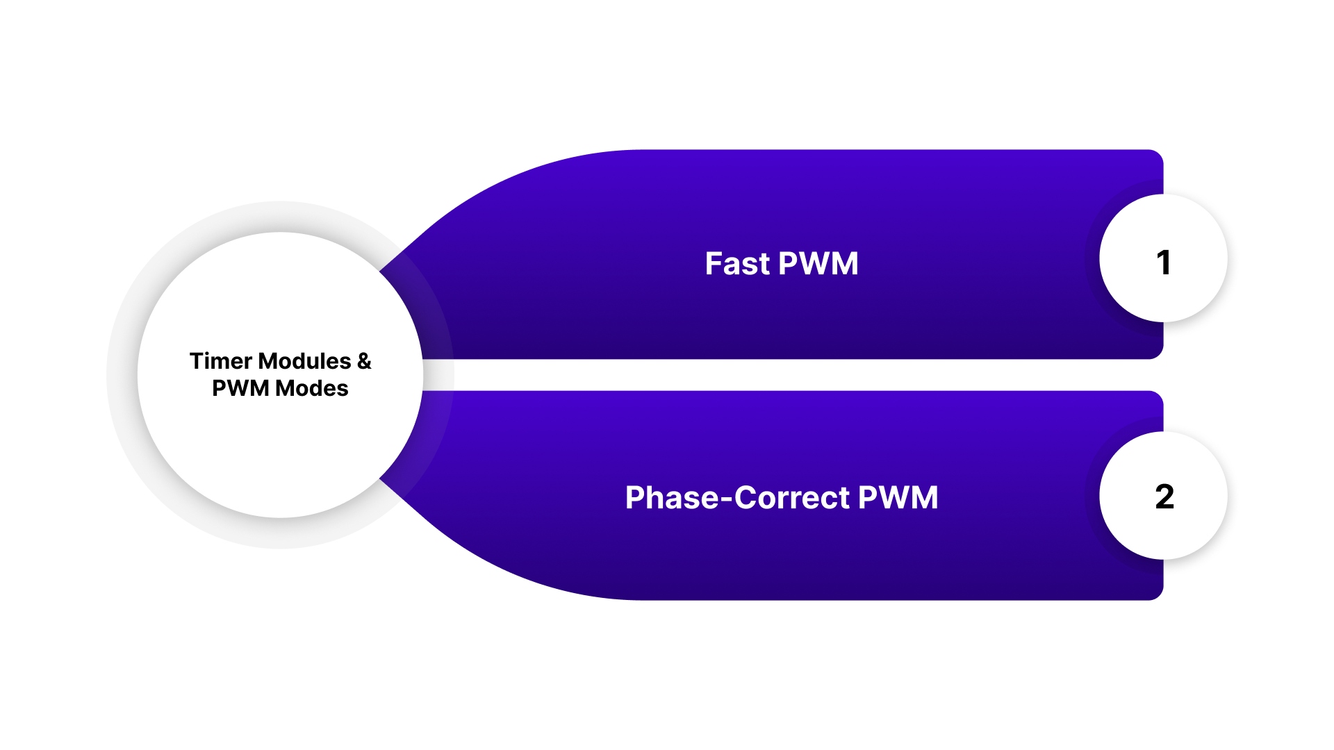
Common PWM modes include:
Fast PWM
The timer counts upward to a maximum value (TOP) and resets. This mode produces a steady, symmetrical waveform and is widely used in motor speed control where responsiveness matters.
Phase-Correct PWM
The timer counts up and down, reducing switching noise and harmonics. While smoother, it operates at half the effective frequency, making it better suited for noise-sensitive applications.
Duty cycle is defined by the ratio between the compare register value and the timer’s maximum count, directly controlling motor speed or torque.
Clock Prescaling and Frequency Control
PWM frequency is determined by three parameters:
System clock speed
Timer TOP value
Prescaler setting
Increasing the prescaler lowers the PWM frequency but reduces resolution. A well-designed pwm motor controller balances frequency and resolution to avoid audible noise while maintaining smooth motor control.
Register Configuration Overview
On AVR-based microcontrollers like the ATmega328P, PWM setup typically involves:
Selecting the PWM mode (Fast or Phase-Correct)
Setting the clock prescaler
Defining the TOP value for frequency control
Assigning compare values for duty cycle
Enabling the PWM output pin
The following example configures Timer1 on an ATmega328P to generate Fast PWM at 1 kHz with a 50% duty cycle, suitable for basic PWM motor controller testing or low-power motor drive applications.
#include <avr/io.h>
void setupPWM() {
// Set OC1A (PB1) as output
DDRB |= (1 << PB1);
// Configure Timer1 for Fast PWM with ICR1 as TOP
TCCR1A = (1 << COM1A1) | (1 << WGM11);
TCCR1B = (1 << WGM13) | (1 << WGM12) | (1 << CS11); // Prescaler = 8
// Set PWM frequency to 1 kHz
// 16 MHz / (8 * (1999 + 1)) = 1 kHz
ICR1 = 1999;
// Set duty cycle to 50%
OCR1A = 999;
}
int main() {
setupPWM();
while (1);
return 0;
}
Once configured, Timer1 generates PWM continuously in hardware, ensuring consistent motor drive signals without CPU intervention.
Advanced PWM Capabilities
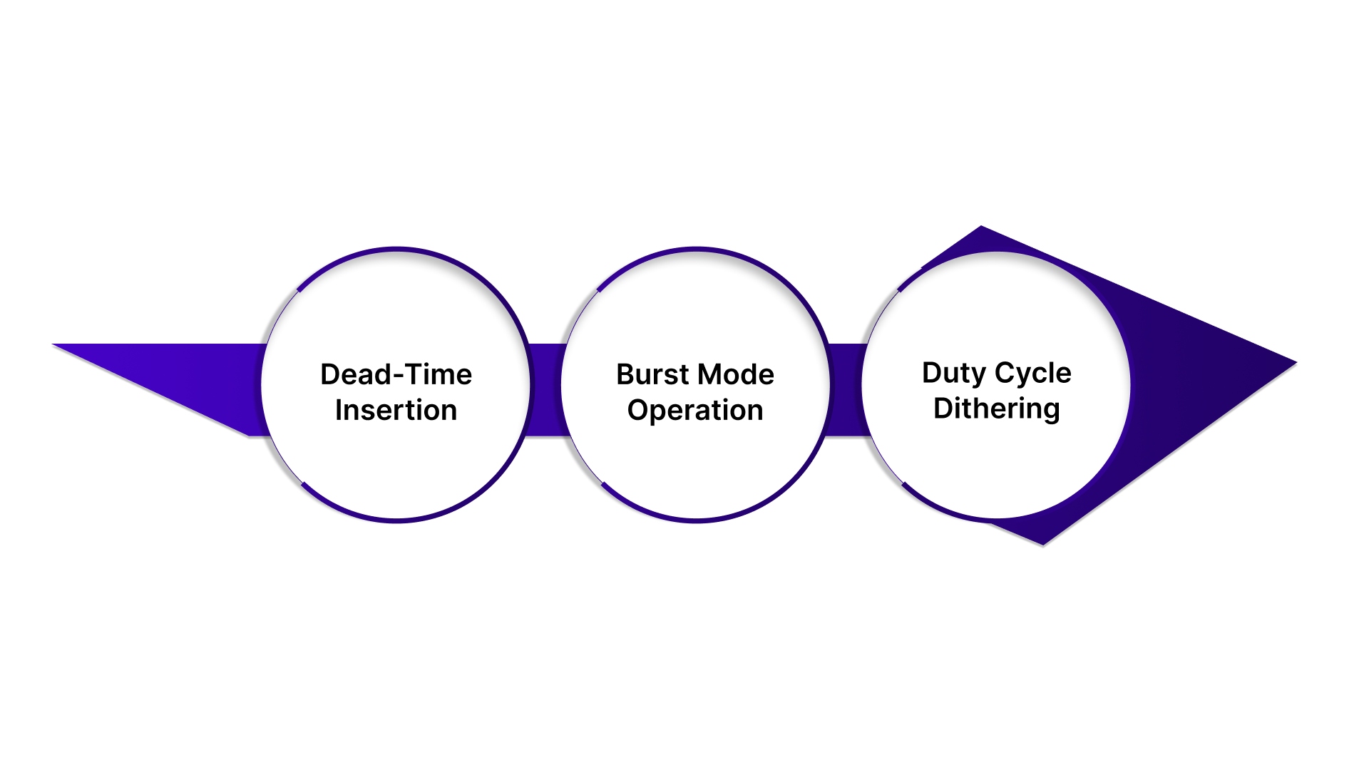
Modern microcontrollers extend PWM functionality well beyond basic duty cycle control:
Dead-Time Insertion – Prevents shoot-through in H-bridge and half-bridge motor drivers
Burst Mode Operation – Reduces power consumption during low-load conditions
Duty Cycle Dithering – Improves effective resolution without increasing timer size
Platforms like STM32 advanced timers or ESP32 PWM units are commonly used in high-performance PWM motor controller designs where precision and efficiency are critical.
Pico Systems PWM Servo Solutions
A reliable PWM motor controller isn’t just about generating pulses, it’s about how those pulses drive real motors, handle feedback, manage power, and stop safely when things go wrong. Pico Systems builds complete PWM servo ecosystems designed to work seamlessly with LinuxCNC and industrial motion setups.
Instead of piecing together mismatched components, Pico Systems offers a hardware stack where every element is designed to work together.
Core PWM Control and Amplification
Universal PWM Controller – Generates precise PWM signals for servo and spindle control, acting as the central control layer.
PWM Servo Amplifier (Brush) – Drives brushed servo motors with stable current and predictable torque response.
Brushless PWM Servo Amplifier – High-efficiency drive for brushless servo motors, supporting smooth commutation and closed-loop control.
Spindle DAC – Converts digital commands into accurate analog spindle control signals.
These components form the backbone of a deterministic PWM motor controller setup, no software timing issues, no unstable pulse generation.
Power, Safety, and Thermal Management
Power Switch and Braking Module – Provides controlled power-up, emergency stop handling, and dynamic braking.
12-V Power Supply – Dedicated auxiliary power for control electronics and logic.
Pre-Drilled Heat Sink for PWM Servo Amps – Ensures reliable thermal dissipation under continuous load.
These modules address the real-world issues PWM systems face: heat, inertia, and safe shutdown.
Feedback and Encoder Integration
Fanuc Encoder Converter
Fanuc Serial Encoder (Pulse Coder) Converter
Panasonic Encoder Converter
These converters allow industrial-grade motors with proprietary encoders to integrate cleanly into modern PWM motor controller architectures, enabling accurate closed-loop motion without replacing existing hardware.
Motors and System Connectivity
Size 23 Brushless Servo Motor – Compact, high-performance motor designed to pair directly with Pico Systems PWM amplifiers.
Connector Panel – Centralizes wiring for cleaner installations and easier maintenance.
Complete PWM Servo Systems – Fully compatible with LinuxCNC for multi-axis motion control.
Together, these components let you build a PWM motor controller system that scales, from a single axis to a full multi-axis machine, without sacrificing timing accuracy or feedback reliability.
Summary
A PWM motor controller is only as reliable as the hardware generating, amplifying, and managing those signals. While microcontrollers can handle basic PWM generation, industrial applications demand deterministic timing, stable power handling, accurate feedback integration, and safe shutdown behavior.
That’s where dedicated PWM servo systems make the difference.
By combining hardware-based PWM generation, robust servo amplifiers, encoder compatibility, braking control, and LinuxCNC integration, Pico Systems removes the guesswork from motor control. The result is predictable motion, cleaner signal paths, and controllers that perform consistently under load, not just in ideal conditions.
If you’re building or upgrading a motion control system and need PWM that works reliably in real machines, Pico Systems provides the complete hardware foundation to make it happen.
Get in touch with us to discuss your application or explore the right PWM servo components for your setup.
FAQs
1. What is a PWM motor controller used for?
A PWM motor controller regulates motor speed, torque, or position by adjusting the duty cycle of a pulse-width modulated signal, commonly used in robotics, CNC machines, and automation systems.
2. Can a microcontroller replace a dedicated PWM controller?
Microcontrollers can generate PWM for basic applications, but dedicated hardware controllers provide more stable timing, better noise immunity, and safer operation for industrial motor control.
3. Why is hardware PWM better for servo motors?
Hardware PWM ensures consistent pulse timing, supports encoder feedback, and integrates braking and fault handling, essential for closed-loop servo control.
4. Do PWM motor controllers work with brushless motors?
Yes. With the correct PWM servo amplifier and commutation method, PWM motor controllers can drive both brushed and brushless servo motors efficiently.
5. How does Pico Systems simplify PWM motor control?
Pico Systems offers complete PWM servo systems, including controllers, amplifiers, encoder converters, braking modules, and motors, designed to work together seamlessly with LinuxCNC.